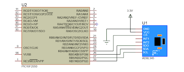
PIC: ADXL345
ADXL345 é um acelerômetro de 3-eixos com alta resolução (13-bit) de medição de até ± 16 g e comunica-se via SPI( 4 ou 3 fios ) ou I2C.
O ADXL345 é bem adequado para aplicações em dispositivos móveis. Ele mede a aceleração estática da gravidade em aplicações tilt-sensing , bem como a aceleração dinâmica resultante do movimento ou choque. Sua alta resolução (3,9 mg / LSB) permite a medição de inclinação menos do que 1.0 °.
PINOS:
| VCC | 3.3V |
| GND | GND |
| SCL | I2C/SPI Clock |
| SDA | I2C Data/ SPI Data Input/ SPI Data InOut |
| SDO | SPI Data Output |
| INT1 | Interrupção 1 |
| INT2 | Interrupção 2 |
| CS | Chip Select |
BIBLIOTECA:
MikroC PRO PIC
#include <Built_in.h>

#define DEVID    0x00 //Device ID
#define THRESH_TAP   0x1D //Tap threshold
#define OFSX    0x1E //X-axis offset
#define OFSY    0x1F //Y-axis offset
#define OFSZ   0x20 //Z-axis offset
#define DUR    0x21 //Tap duration
#define LATENT   0x22 //Tap latency
#define WINDOW   0x23 //Tap window
#define THRESH_ACT   0x24 //Activity threshold
#define THRESH_INACT  0x25 //Inactivity threshold
#define TIME_INACT   0x26 //Inactivity time
#define ACT_INACT_CTL  0x27 //Axis enable control for activity and inactivity detection
#define THRESH_FF  0x28 //Free-fall threshold
#define TIME_FF   0x29 //Free-fall time
#define TAP_AXES   0x2A //Axis control for single tap/double tap
#define ACT_TAP_STATUS  0x2B //Source of single tap/double tap
#define BW_RATE   0x2C //Data rate and power mode control
#define POWER_CTL   0x2D //Power-saving features control
#define INT_ENABLE   0x2E //Interrupt enable control
#define INT_MAP   0x2F //Interrupt mapping control
#define INT_SOURCE   0x30 //Source of interrupts
#define DATA_FORMAT  0x31 //Data format control
#define DATAX0    0x32 //X-Axis Data 0 //Hi
#define DATAX1    0x33 //X-Axis Data 1 //Low
#define DATAY0    0x34 //Y-Axis Data 0
#define DATAY1    0x35 //Y-Axis Data 1
#define DATAZ0    0x36 //Z-Axis Data 0
#define DATAZ1    0x37 //Z-Axis Data 1
#define FIFO_CTL   0x38 //FIFO control
#define FIFO_STATUS  0x39 //FIFO status

#define ADXL345_SDO SoftSpi_SDO
#define ADXL345_CLK SoftSpi_CLK
#define ADXL345_SDI SoftSpi_SDI
#define ADXL345_SDO_Direction SoftSpi_SDO_Direction
#define ADXL345_CLK_Direction SoftSpi_CLK_Direction
#define ADXL345_SDI_Direction SoftSpi_SDI_Direction


typedef struct
{
 signed int X;
 signed int Y;
 signed int Z;
}ADXL345;

static void ADXL345_Write( char addr, char value )
{
 ADXL345_CS = 0;
 Soft_SPI_Write( addr | 0x80 );
 Soft_SPI_Write( value );
 ADXL345_CS = 1;
}

static void ADXL345_Rd( char addr, char len, char *outData )
{
char i;
 addr |= 0x80;
 if( len > 1) addr |= 0x40;

 ADXL345_CS = 0;
 Soft_SPI_Write( addr );
 for( i=0; i < len; i++ )
 {
    outData[i] = Soft_SPI_Read( 0x00 );
 }
 ADXL345_CS = 1;
}

void ADXL345_Init()
{
 ADXL345_CS_Direction = 0;
 ADXL345_CS = 1;

 ADXL345_Write( POWER_CTL, 0x00 ); // Modo Inicial em StandBy
 ADXL345_Write( DATA_FORMAT, 0x0B );// Full resolution, +/-16g, 4mg/LSB. SPI 4-Wire
 ADXL345_Write( BW_RATE, 0x0F); // Buffer Speed - 3200Hz
 ADXL345_Write( POWER_CTL, 0x08); // Measurement mode.
}

void ADXL345_Read( ADXL345 *Accel )
{
char dat[6];
 ADXL345_Rd( DATAX0, 6, &dat );
 Accel->X = ( dat[0] << 8 ) | dat[1];
 Accel->Y = ( dat[2] << 8 ) | dat[3];
 Accel->Z = ( dat[4] << 8 ) | dat[5];
}
EXEMPLO:
//Habilitar as seguintes bibliotecas:
// - Soft_SPI
// - Uart
// - Conversions e C_String

sbit ADXL345_CS at  RB4_Bit;
sbit ADXL345_SDO at RB5_Bit;
sbit ADXL345_CLK at RB6_Bit;
sbit ADXL345_SDI at RB7_Bit;
sbit ADXL345_CS_Direction at TRISB4_Bit;
sbit ADXL345_SDO_Direction at TRISB5_Bit;
sbit ADXL345_CLK_Direction at TRISB6_Bit;
sbit ADXL345_SDI_Direction at TRISB7_Bit;

//Copie e cole a biblioteca aqui

ADXL345 Accel;

char out[8];

void main()
{
    Soft_SPI_Init();
    ADXL345_Init();
    UART1_Init(9600);

    while(1)
    {
            ADXL345_Read( &Accel );

            Uart1_Write_Text( "X: " );
            IntToStr( Accel.X, out );
            Uart1_Write_Text( out );
            Uart1_Write( 13 );
            Uart1_Write( 10 );

            Uart1_Write_Text( "Y: " );
            IntToStr( Accel.Y, out );
            Uart1_Write_Text( out );
            Uart1_Write( 13 );
            Uart1_Write( 10 );

            Uart1_Write_Text( "Z: " );
            IntToStr( Accel.Z, out );
            Uart1_Write_Text( out );
            Uart1_Write( 13 );
            Uart1_Write( 10 );

            Delay_ms( 500 );
    }
}


O SCL, SDA e SDO podem ser ligados diretamente ao PIC? Não seria necessária a conversão da saída do PIC para 3V e da saída do acelerômetro para 5V?
ResponderExcluirDepende do módulo que você está utilizando...a maioria pode ser ligada diretamente ao PIC.
ExcluirOlá,
ResponderExcluirExiste alguma biblioteca com acelerômetro para o Proteus? Caso exista, onde posso encontrar?
Obrigado
Como ficaria para detectar uma queda do equipamento? Vi que esse acelerômetro tem um pino de interrupção caso ele detecte queda mas não consegui implementar, você pode mostrar um exemplo?
ResponderExcluirHi, sorry but could u tell me how can I add adxl345 component in proteus?thanx in advance
ResponderExcluirOlá!!! Muito bom seu artigo, foi o único que achei para pic18. Obrigado. Eu estou usando o mikroc para programar e quando tento compilar ele retorna com o seguinte erro:
ResponderExcluirUndeclared identifier 'ADXL345_CS' in expression source_PIC073_WR.c
Não estou entendo o que é! Pode me ajudar?
Obrigado.
Copie e cole a biblioteca antes da linha 6 do Exemplo...
Excluir